Computer simulation tools for Mechanical Engineers have been around for the last thirty years or so, holding a reputation of being difficult and ruinously expensive. Today they encompass mainstream techniques used in nearly every industry.
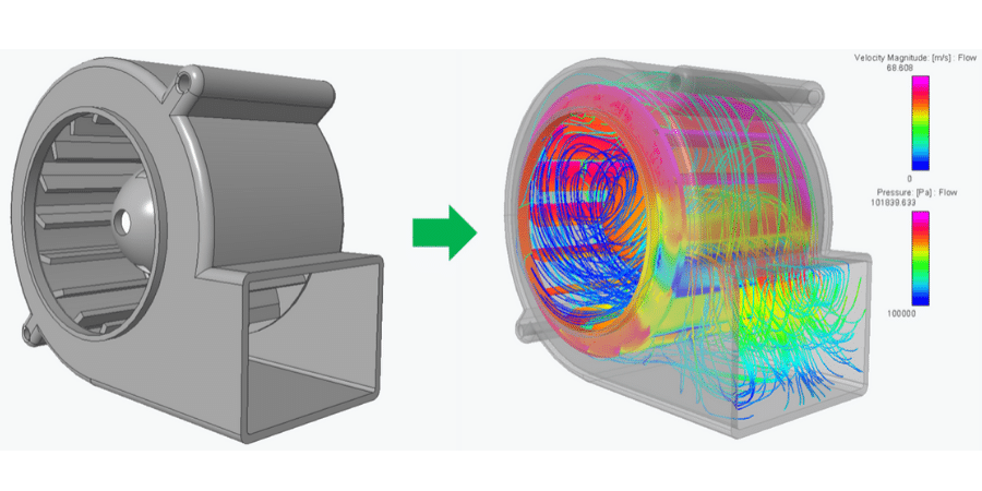
 PTC offers a tool called Creo Simulate, formerly Pro/Mechanica, which performs “Finite Element Analysis” on structural and thermal conduction designs. Technically, Creo Simulate is Geometric Element Analysis (GEA), which differs from FEA by using variable order elements, also known as P-Method elements. When combined with the standard two-pass iterative solver these elements provide the same capability as adaptive meshing and a non-linear solver with shorter run times and a much lower investment.
So, how do you get the best value from an FEA Tool? Select one that can be used early and often. This will help you:
- Make better design decisions than you can do using conventional techniques, such as hand calculations or guesswork.
- Ideally, you want the ability to run a simulation in less time than a hand calculation would take. Speed is achieved by reliable auto-meshing, and by running the entire simulation in the CAD Environment.
- Accommodate changes even faster than the first analysis. This is possible because boundary conditions are applied to geometry instead of mesh, so one can modify the parametric solid model and then re-run the analysis with little or no additional work. Mesh refinement is rules-based, so good quality mesh is produced, even when significant changes are made to geometry.
- Ability to do sensitivity studies and optimizations. With these techniques, dimensional changes to parametric geometry are driven by the simulation, so multiple shapes can be considered in a single simulation.
- Running simulation early saves work. Fully detailed solid models have to be “de-featured”, to remove fillets and small holes, then meshed and run. If you run Creo Simulate early in the design process, you don’t spend time removing small features, because they haven’t been added yet.
- Running simulation often produces a better design in less time. For simple geometry, one can go through the whole cycle of imagining an improvement, modifying or adding to the solid model, re-running the analysis, and drawing conclusions from the results in less than an hour. This means that you can make several design turns in a single day without cutting any metal. Building and testing this many physical prototypes would take months and cost thousands of dollars more.
Engineering design has been described as “the art of getting rid of the stupidest design ideas at the lowest possible cost, and then concentrating effort on the smartest ideas”. Creo Simulate is an effective tool to do just this, providing you apply it early, believe what it’s telling you, and act on the information.
By William Stickney
About the Contributor – Bill has Twenty years experience with FEA in aerospace structures and electronics packaging. He is an expert in nonlinear static, dynamic, and thermal FEA with 2D, Shell, and Solid elements. His experience includes working on static, vibration mode, and random vibration analysis of aerospace structures and has extensively used tools such as Abaqus, (MSC) Marc Analysis, (PTC) Pro/Mechanica and Altair Hypermesh.
Bill is currently an Instructor and Engineering Consultant for 3 HTi (a Systems Integrator for Product Development and PLM Solutions). Of his many areas of expertise, he excels at software simulation for new product development or improvement of existing products, the development of new electrical materials (including design of testing equipment and software) and the design of electronic packaging for aerospace applications.